TB-RK3588X Introduction
TB-RK3588X use Rockchip’s latest flagship SOC chip RK3588. RK3588 is a general-purpose SoC based on ARM architecture, integrating quad-core Cortex-A76 and quad-core Cortex-A55 CPU, G610 MP4 graphics processor.
RK3588 built-in a variety of powerful embedded hardware engines, supporting 8K@60fps h.265 and VP9 decoders, 8K@30fps H.264 decoder and 4K@60fps AV1 decoder; Supports 8K@30fps h.264 and H.265 encoders, high quality JPEG encoders/decoders, specialized image preprocessors and post-processors.
The build-in NPU supports INT4/INT8/INT16/FP16 hybrid operation and computing power is up to 6TOPs. In addition, with its strong compatibility, network models based on a series of frameworks such as TensorFlow/MXNet/PyTorch/Caffe can be easily converted.
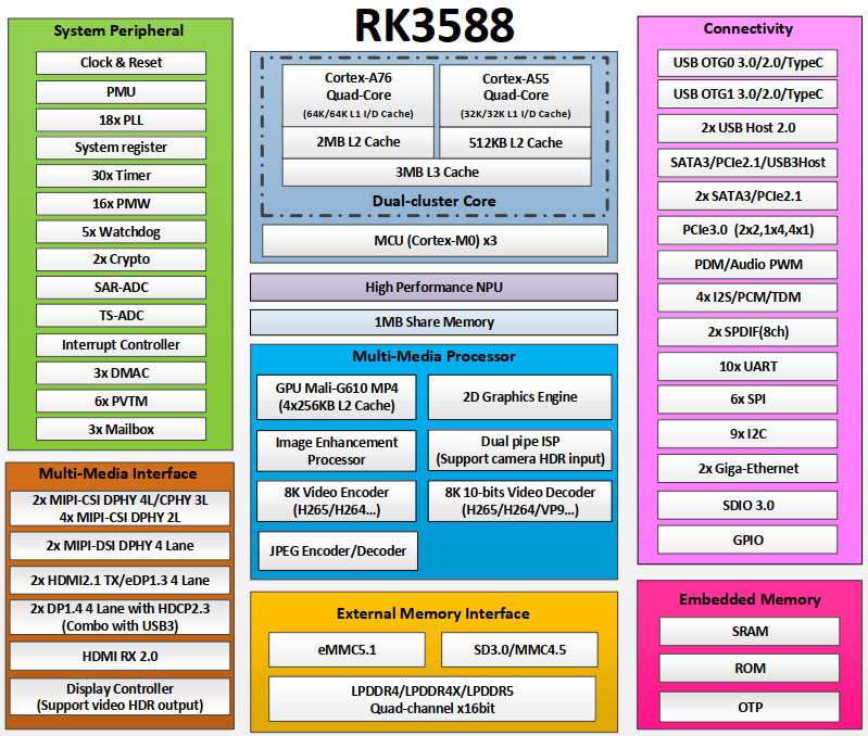
TB-RK3588X adopts core board and mainboard design. The core board is connected with the mainboard through the MXM314Pin standard interface, which can form a complete industry development board. TB-RK3588X has a abundant expansion interface, which maximizes the high-performance advantages of RK3588, and can be directly used in the development of various intelligent products to speed up product implementation.

TB-RK3588X Standard Kit
The TB-RK3588X standard kit contains the following accessories:
TB-RK3588C0 core board x 1
TB-RK3588B0 mainboard × 1/TB-RK3588B1 mainboard× 1(TB-RK3588B1 is upgrated version of TB-RK3588B0)
12V/2A power adapter x 1
FAN x 1
Type-C data cable x 1
Optional accessories include:
Display device
Monitor or TV with HDMI connector and HDMI cable.
Network
100M/1000M Ethernet cable and wired router
WiFi router
Input device
USB wireless/wired mouse/keyboard
Update firmware, debug device
Micro USB data cable
Assembly Introduction
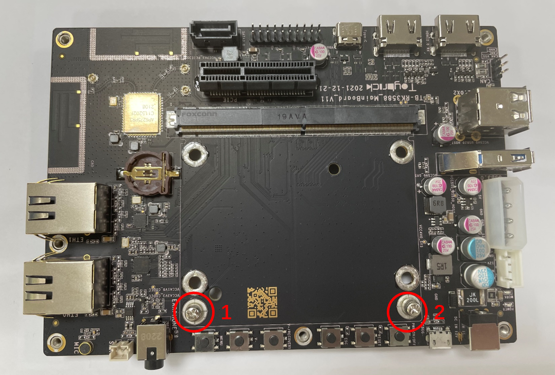
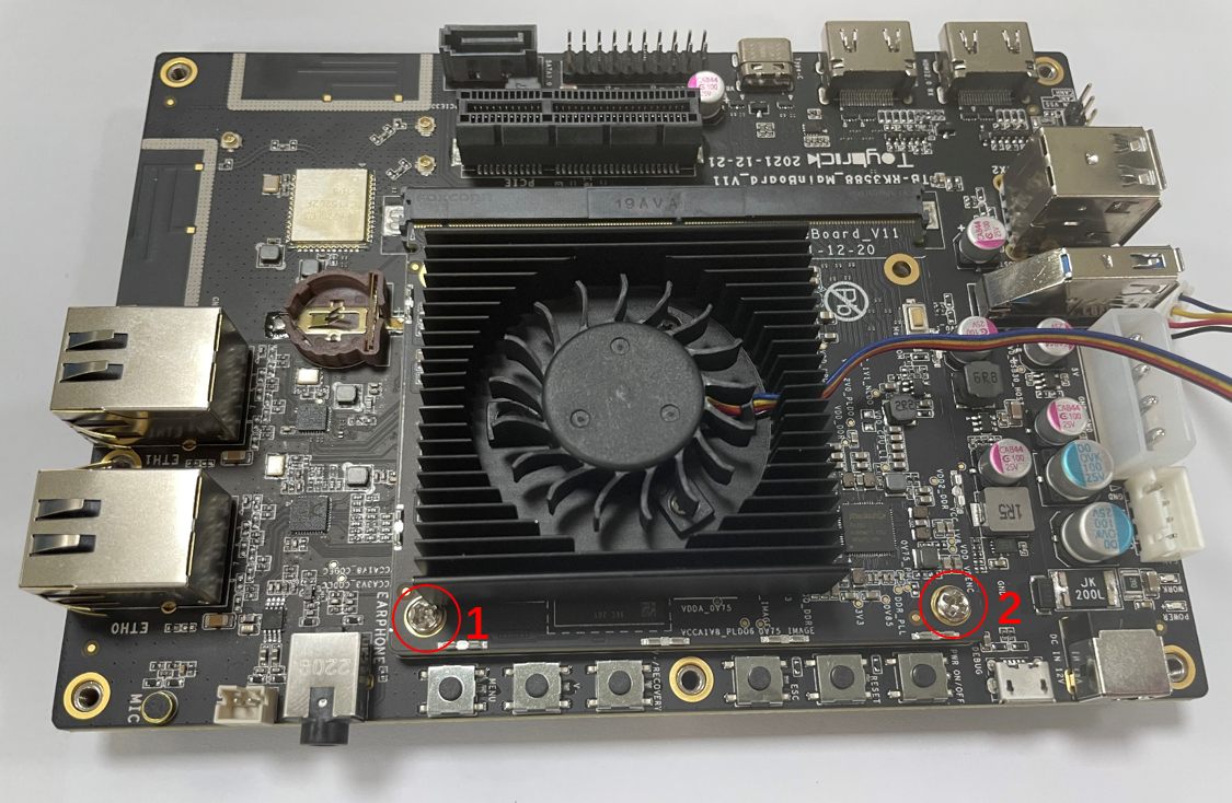
Remove screws no. 1 and 2 from the TB-RK3588X mainboard.
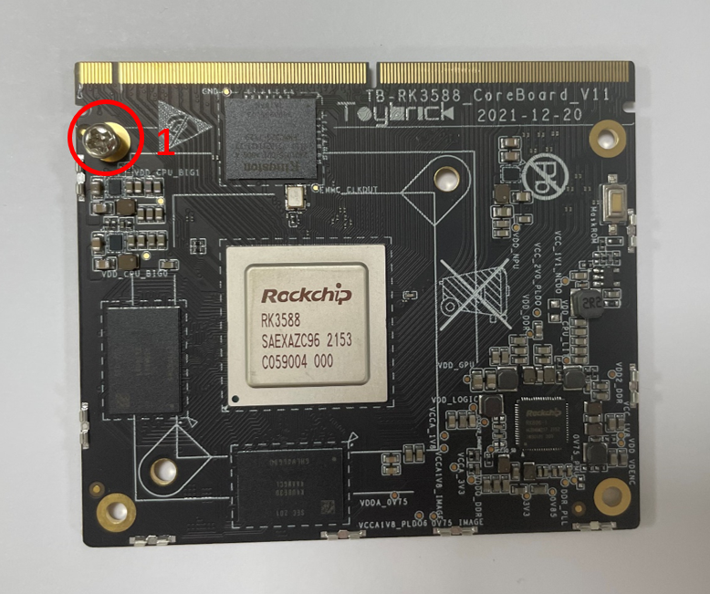
Install no. 1 screw on TB-RK3588X coreboard.
Take out the fan accessories and align the screw holes of the fan on the coreboard.
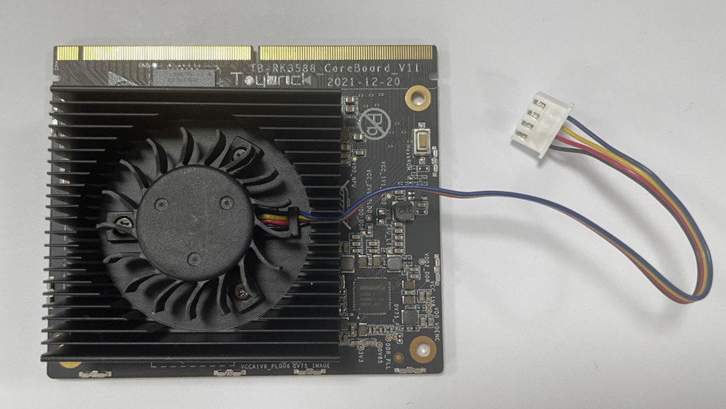
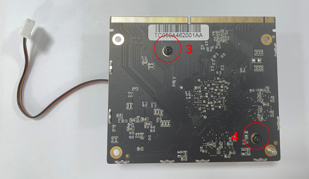
Take out fan’s screws no. 3 and 4 and lock the screws from the back of the coreboard.
Install the coreboard on the mainboard, and lock screws no. 1 and 2.
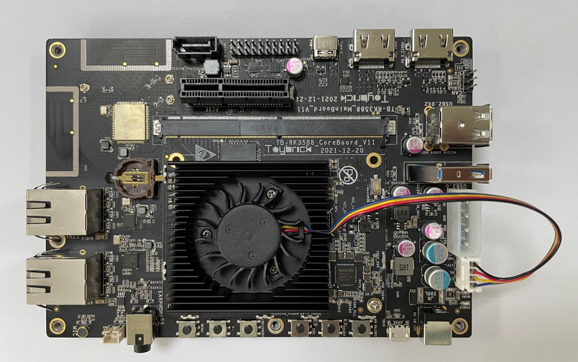
Connect the fan power cable to the pins as the following figure to complete the installation.
Serial Debug
Serial Port Connect
Connecting PC USB host port and TB-RK3588X debug port with MicroUSB cable.

Note: Usually the debug port on development board has “DEBUG” or “UART TO USB” silkscreen.
Use Serial Debug on Windows
Install Driver
The USB to serial port chip on TB-RK3588 is FT232. If the operating system prompts you to install a driver, download the driver or use the Driver Genius to install the driver.
Get Port
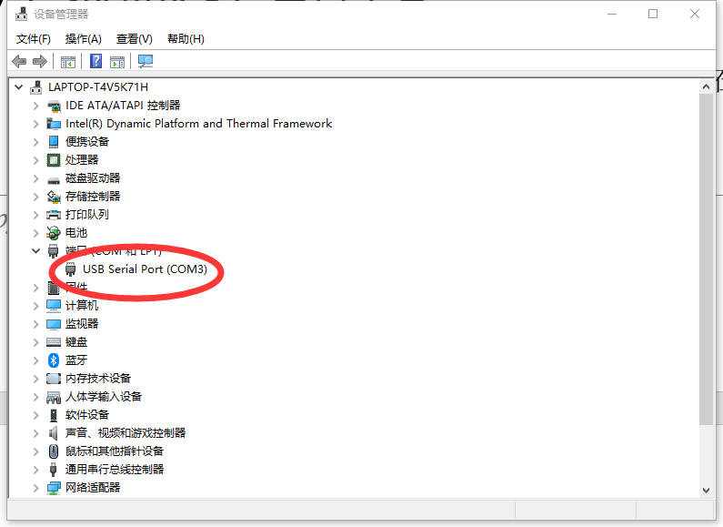
Open Windows Device Manager to get the port of USB serial port, as shown in figure 1-1:
Port Setting
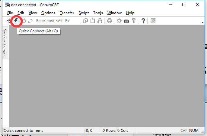
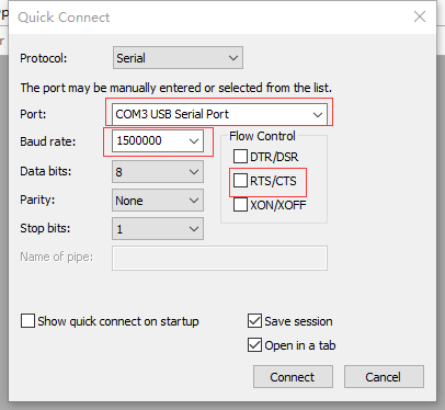
Open SecureCRT(download by yourself ), click “Quick Connect” button to configure serial, as shown in figure 1-2 and figure 1-3:
Port: Set the port number what we get from Windows Device Manager.
Baud rate: Shoud be set 1500000.
Disable flow control: Do not select RTS/CTS.
Use Serial Debug on Linux
Install Minicom
sudo apt -y install minicom
Port Setting
According to the following steps to configure the serial port information.
提示
Only need to execute the steps for the first time!
Obtain the device node after inserting the serial port debugging cable, if it is not
ttyUSB0, please modify the configuration value ofminicomaccordingly.$ls /dev/ttyUSB* /dev/ttyUSB0
Execute the following command to open
minicom.sudo minicom -s
Press CTRL-A Z, enter serial setting interface.
+-------------------------------+
| Filenames and paths           |
| File transfer protocols       |
| Serial port setup             |
| Modem and dialing             |
| Screen and keyboard           |
| Save setup as dfl             |
| Save setup as                 |
| Exit                          |
+-------------------------------+
Port setting: select
Serial port setup.Port device setting: Press “A”, input
/dev/ttyUSB0, and then press “ENTER”.Disable flow control:Press “F”,and then press “ENTER”.
Baud rate setting: Press “E”, and then press “A” to swtich baud rate, until it shows Current
1500000 8N1, then press “ENTER”.Port setting as shown bellow:
+--------------------------------------------------------+
| A -        Serial Device          : /dev/ttyUSB0       |
| B -        Lockfile Location      : /var/lock          |
| C -        Callin Program         :                    |
| D -        Callout Porgram        :                    |
| E -        Bps/Par/Bits           : 1500000 8N1        |
| F -        Hardware Flow Control  : No                 |
| G -        Software Flow Control  : No                 |
+--------------------------------------------------------+
Exit port setting: Press “ENTER” to return.
Save configuration: Select
Save setup as dfl.Exit setting: Selct
Exit.
Runnning Minicom
sudo minicom
Upgrade Images
TB-RK3588x default pre-installed debian11 OS, If you need to run other OS, download the corresponding firmware and flash it to the board.
If bootloader verification fails, cannot enter the loader mode during the upgrade process, you can enter MaskRom mode to flash image.
How to Get the Images
TB-RK3588X0 (TB-RK3588X0-IMAGES.tar.gz) download link:
Enter Upgrade Mode
Prepare
TB-RK3588x development board
PC host
Type-C data cable
12v power adapter
Install Windows RK USB Driver
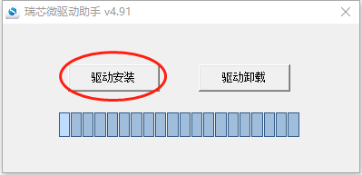
Download Flashtool RAR, uncompress in directory FlashTool_CN.zip\FlashTool_CN\Windows\DriverAssitant. Execute DriverInstall.exe. Select驱动卸载, then select驱动安装.
Enter Loader Upgrade Mode
Connecting PC USB Host and development board Type-C with Type-C cable, long press V+/Recovery button.
The development board with 12V power supply. If it is powered on, press the reset button.
When development board entered loader mode, release the button.
Please refer to “Check the flash status” section to check whether the development board is enter loader mode.
Enter Maskrom Upgrade Mode
Connecting PC USB Host and development board Type-C with Type-C cable, long press Maskrom button.
The development board with 12V power supply. If it is powered on, press the reset button.
When development board entered loader mode, release the button.
Please refer to “Check the flash status” section to check whether the development board is enter Maskrom mode.

Check Upgrade Status
Check Upgrade Status by Linux Host
Download the edge tool (please download the linux BSP firstly) , Execute the following command to check upgrade status.
./edge flash -q
none: Indicating that the development board is not in upgrade mode.
loader: Indicating that the development board entered loader mode.
maskrom: Indicating that the development board entered maskrom mode.
Check Upgrade Status by Windows Host
Download RKDevTool_Release_v2.84 tool.
Open RKDevTool.exe in tools\RKDevTool_Release_v2.84 directory.
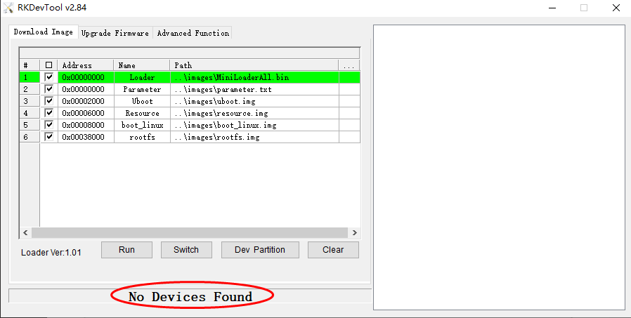
No devices found (as shown in Figure 1-4): Indicating that the development board is not in upgrade mode.
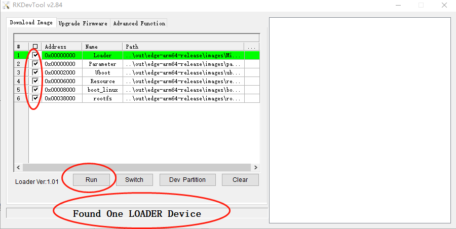
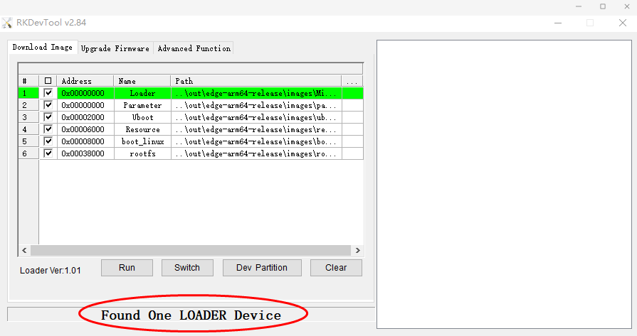
Found a LOADER device (as shown in Figure 1-5): Indicating that the development board entered loader mode.
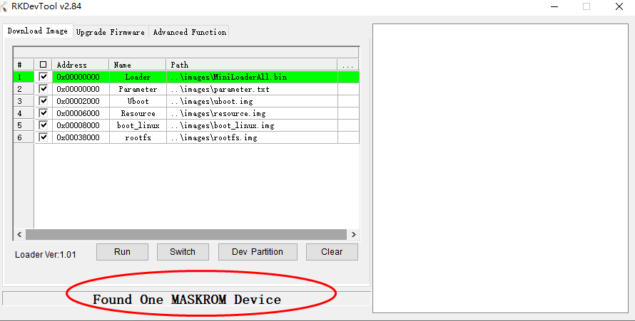
Found One MASKROM Device (as shown in Figure 1-6): Indicating that the development board entered maskrom mode.
Upgrade Images via Linux Hsot
Upgrade All Images
Flash those images:MiniLoaderAll.bin, uboot.img, resource.img, boot_linux.img,rootfs.img and parameter.txt
./edge flash -a
Upgrade Uboot Image
Flash images: MiniLoaderAll.bin, uboot.img and parameter.txt
./edge flash -u
Upgrade Kernel Image
Flash those images: boot_linux.img和resource.img
./edge flash -k
Upgrade Rootfs
./edge flash -r
Help
Execute the following command to view the supported flash parameters.
./edge flash -h
Upgrade Images via Windows Host
Open RKDevTool.exe in tools\RKDevTool_Release_v2.84 directory.
Verify development board has entered loader or maskrom mode.
Select the needed images to flash
注解
Loader and Parmeter are recommended, other options selected as needed.
Click “Execute” button to start flash images. (as shown in figure1-7).
