TB-RK3588SD Introduction
TB-RK3588SD development board is a development board that integrates reference design, chip debugging and testing, and chip verification for RK3588S chip. It is used to show the powerful multimedia interface and rich peripheral interface of the RK3588S chip. It also provides hardware reference design based on the RK3588S chip, enabling developers to complete their hardware development without modifying or only making simple modifications to the module circuits of the reference design.
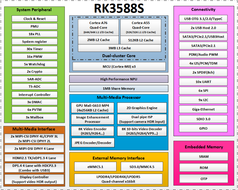
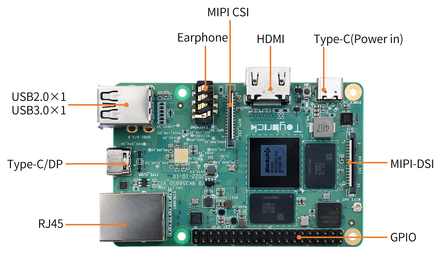
TB-RK3588SD compact layout, rich interface, support Gigabit network port, HDMI, MIPI-DSI, onboard WIFI, USB3.0 and other interfaces, equipped with 4GB/8GB LPDDR4X memory. The PCB size is only 89mm x 57mm, and the 40Pin GPIO is perfectly compatible with the Raspberry PI. Can be widely used in AI, cloud computing, AR/VR, game interaction, network broadcast, conference projection screen and other intelligent upgrade related industry applications.
TB-RK3588SD Standard Kit
The TB-RK3588SD standard kit contains the following accessories:
TB-RK3588SD development board x 1
Additionally, you may need the following accessories during usage:
Display device
Monitor or TV with HDMI connector and HDMI cable.
Network
100M/1000M Ethernet cable and wired router
WiFi router
Input device
USB wireless/wired mouse/keyboard
Debug device
Dupont wires, used as serial port debugging cables
USB-to-serial converter board
Serial Debug
Serial Port Connect
Connect the TB-RK3588SD using Dupont wires and a USB-to-serial converter board (with the CH340 USB-to-serial chip) at the location shown in the diagram below. The USB-to-serial converter board is then connected to the computer via a USB cable.

Note: If the TB-RK3588SD is used together with TB-RK3588SD-POWER power board, connect the debug port of the power board using a micro USB cable.(Usually the debug port on development board has “DEBUG” or “UART TO USB” silkscreen.)
Use Serial Debug on Windows
Install Driver
After connecting the serial port of the TB-RK3588SD, if the operating system prompts you to install a driver, download the driver or use the Driver Genius to install the driver.
Get Port
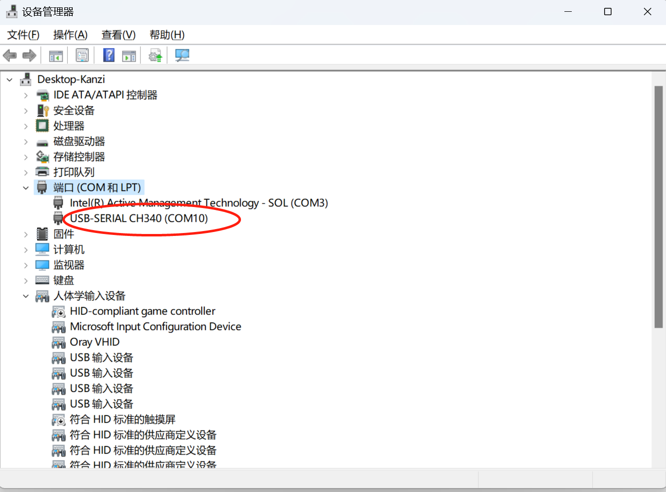
Open Windows Device Manager to get the port of USB serial port, as shown in figure 1-1:
Port Setting
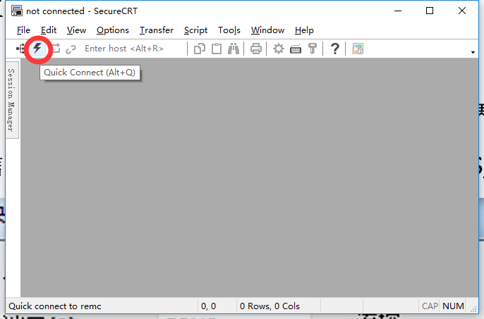
Open SecureCRT(download by yourself ), click “Quick Connect” button to configure serial, as shown in figure 1-2 and figure 1-3:
Port: Set the port number what we get from Windows Device Manager.
Baud rate: Shoud be set 1500000.
Disable flow control: Don’t select RTS/CTS.

Use Serial Debug on Linux
Install minicom
sudo apt -y install minicom
Port Setting
According to the following steps to configure the serial port information.
提示
Only need to execute the steps for the first time!
Obtain the device node after inserting the serial port debugging cable, if it is not
ttyUSB0, please modify the configuration value ofminicomaccordingly.$ls /dev/ttyUSB* /dev/ttyUSB0Execute the following command to open
minicom.sudo minicom -s
Press CTRL-A Z, enter serial setting interface.
+-------------------------------+
| Filenames and paths           |
| File transfer protocols       |
| Serial port setup             |
| Modem and dialing             |
| Screen and keyboard           |
| Save setup as dfl             |
| Save setup as                 |
| Exit                          |
+-------------------------------+
Port setting: select
Serial port setup.Port device setting: Press “A”, input
/dev/ttyUSB0, and then press “ENTER”.Disable flow control:Press “F”,and then press “ENTER”.
Baud rate setting: Press “E”, and then press “A” to swtich baud rate, until it shows Current
1500000 8N1, then press “ENTER”.Port setting as shown bellow:
+--------------------------------------------------------+
| A -        Serial Device          : /dev/ttyUSB0       |
| B -        Lockfile Location      : /var/lock          |
| C -        Callin Program         :                    |
| D -        Callout Porgram        :                    |
| E -        Bps/Par/Bits           : 1500000 8N1        |
| F -        Hardware Flow Control  : No                 |
| G -        Software Flow Control  : No                 |
+--------------------------------------------------------+
Exit port setting: Press “ENTER” to return.
Save configuration: Select
Save setup as dfl.Exit setting: Selct
Exit.
Runnning minicom
sudo minicom
Partition Configuration
For the TB-RK3588SD0 to normally boot the Debian system, images need to be burned onto both the SpiFlash and the TF card.
Partition information for SpiFlash, including partition name, start address, and partition size (with the start address and partition size given in blocks, where each block is 512 bytes). The TB-RK3588SD0 loads the part-fit partition table, with the partition table information as follows:
| configuration item | description | start adress | partition size | note |
|---|---|---|---|---|
| vnvm | vnvm partition | 0x00000500 | 0x00000500 | Required option |
| uboot | uboot partition | 0x00000a00 | 0x00000800 | Required option |
| boot | boot partition | 0x00001200 | - | All remaining space, is required |
The TF card only needs to be formatted into one ext4 partition for storing the Rootfs file system.
提示
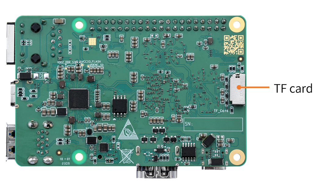
The TF card pre-installed with the Rootfs file system does not support hot plugging. Please insert the TF card after powering off, and then power on to enter the system!
Upgrade Images
The TB-RK3588SD default pre-installed SpiFlash image . If you need to run the Debian system, please insert the TF card with the rootfs burned into the development board and power it on to start. If an unexpected situation occurs during the upgrade process and you are unable to enter the loader burning mode, you can still enter MaskRom mode to burn the firmware.
How to Get the Images
TB-RK3588SD (TB-RK3588SD-IMAGES.tar.gz)download link:
Enter Upgrade Mode
Prepare
TB-RK3588SD development board
PC Host
Type-C data cable
Install Windows RK USB Driver
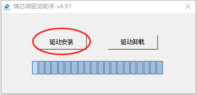
Download Flashtool RAR, uncompress in directory FlashTool_CN.zip\FlashTool_CN\Windows\DriverAssitant. Execute DriverInstall.exe. Select驱动卸载, then select驱动安装.
Enter Loader Upgrade Mode
Connect one end of the Type-C cable to the “TYPE_C/DP” port on the development board, and the other end to the USB port on the PC side.
Hold down the “REC_KEY” button on the board and re-plug the Type-C cable on the development board side.
Release the button when the development board enters loader mode.
Enter Maskrom Upgrade Mode
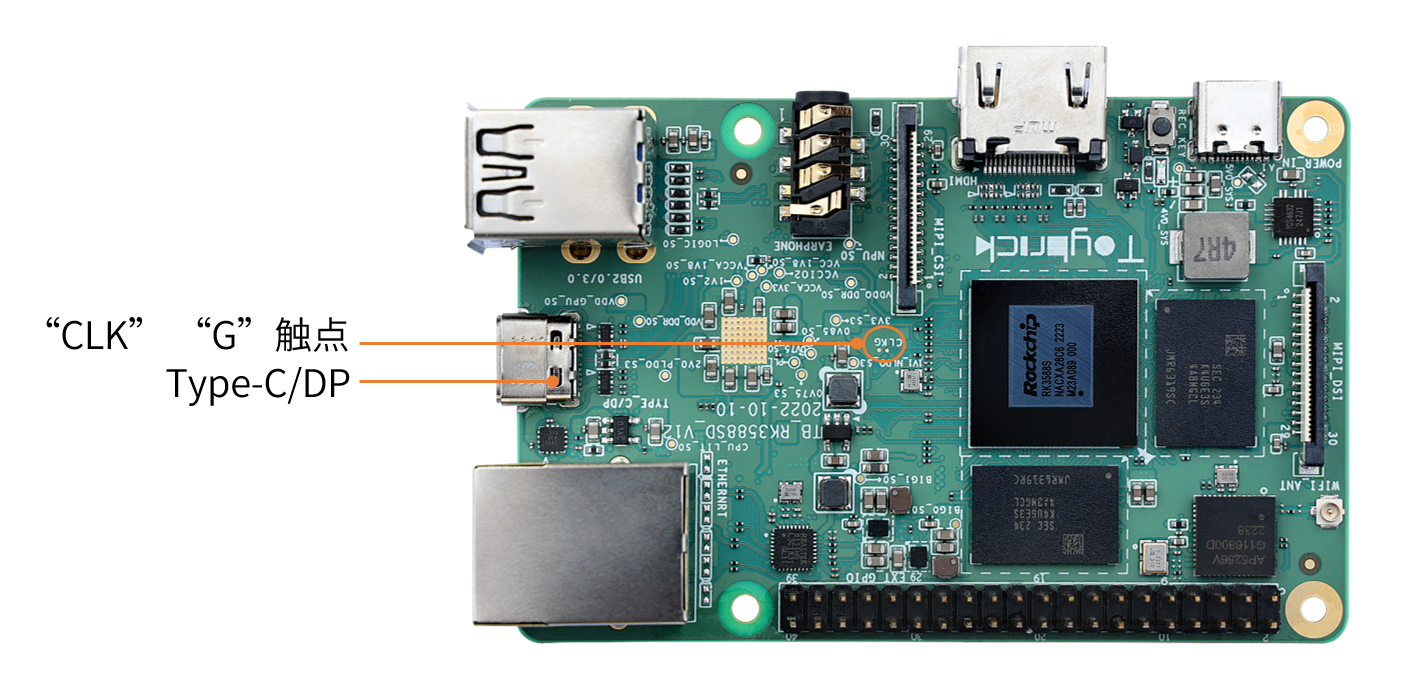
Connect one end of the Type-C cable to the “TYPE_C/DP” port on the development board, and the other end to the USB port on the PC side.
Use a tweezer to short-circuit the two contact points labeled “CLK” and “G” on the board and re-plug the Type-C cable on the development board side.
Release the tweezer when the development board enters maskrom mode.
Check Upgrade Status
Check Upgrade Status by Linux Host
Download the edge tool (please download the linux BSP firstly) , Execute the following command to check upgrade status.
./edge flash -q
none: Indicating that the development board is not in upgrade mode.
loader: Indicating that the development board entered loader mode.
maskrom: Indicating that the development board entered maskrom mode.
Check Upgrade Status by Windows Host
Download RKDevTool_Release_v2.84 tool.
Open RKDevTool.exe in tools\RKDevTool_Release_v2.84 directory.
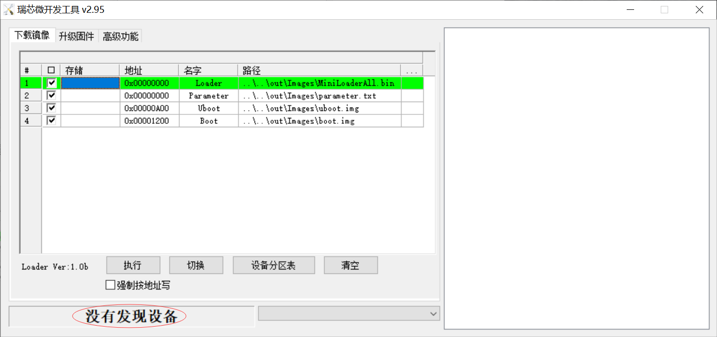
No devices found (as shown in Figure 1-4): Indicating that the development board is not in upgrade mode.
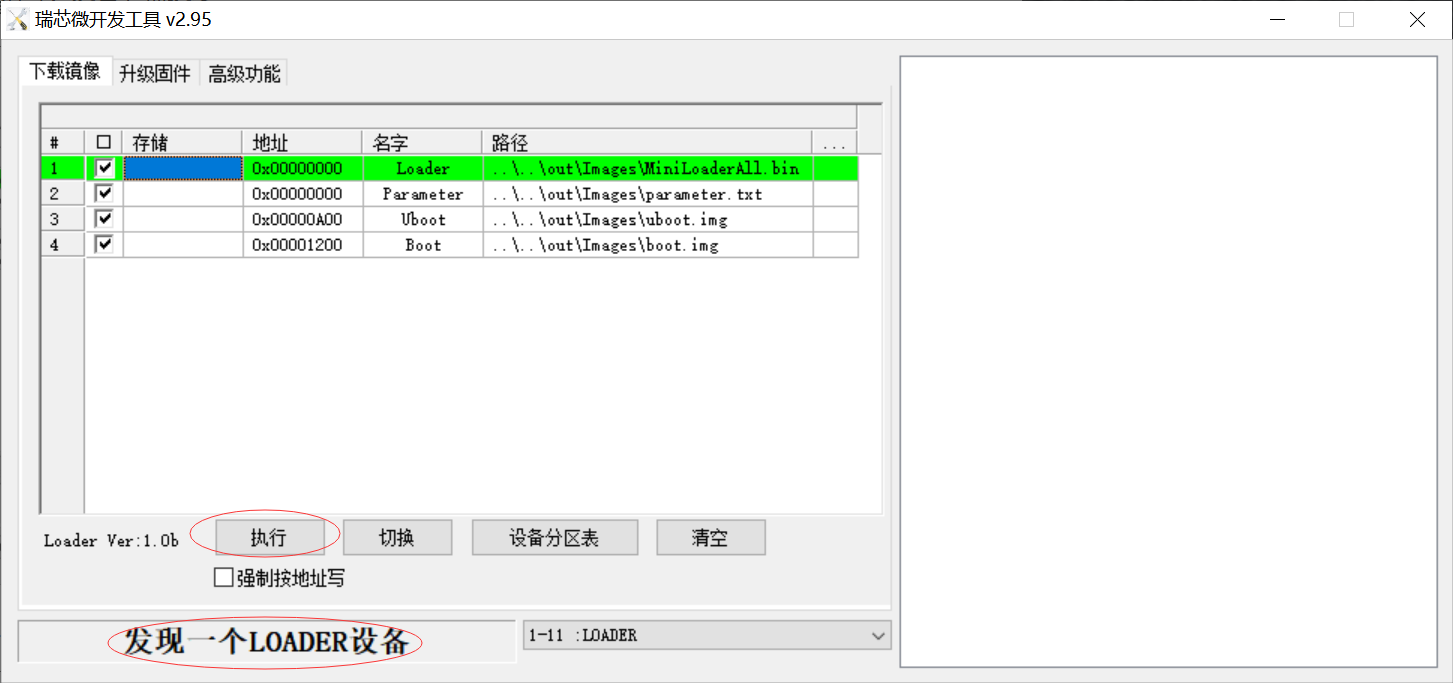
Found a LOADER device (as shown in Figure 1-5): Indicating that the development board entered loader mode.
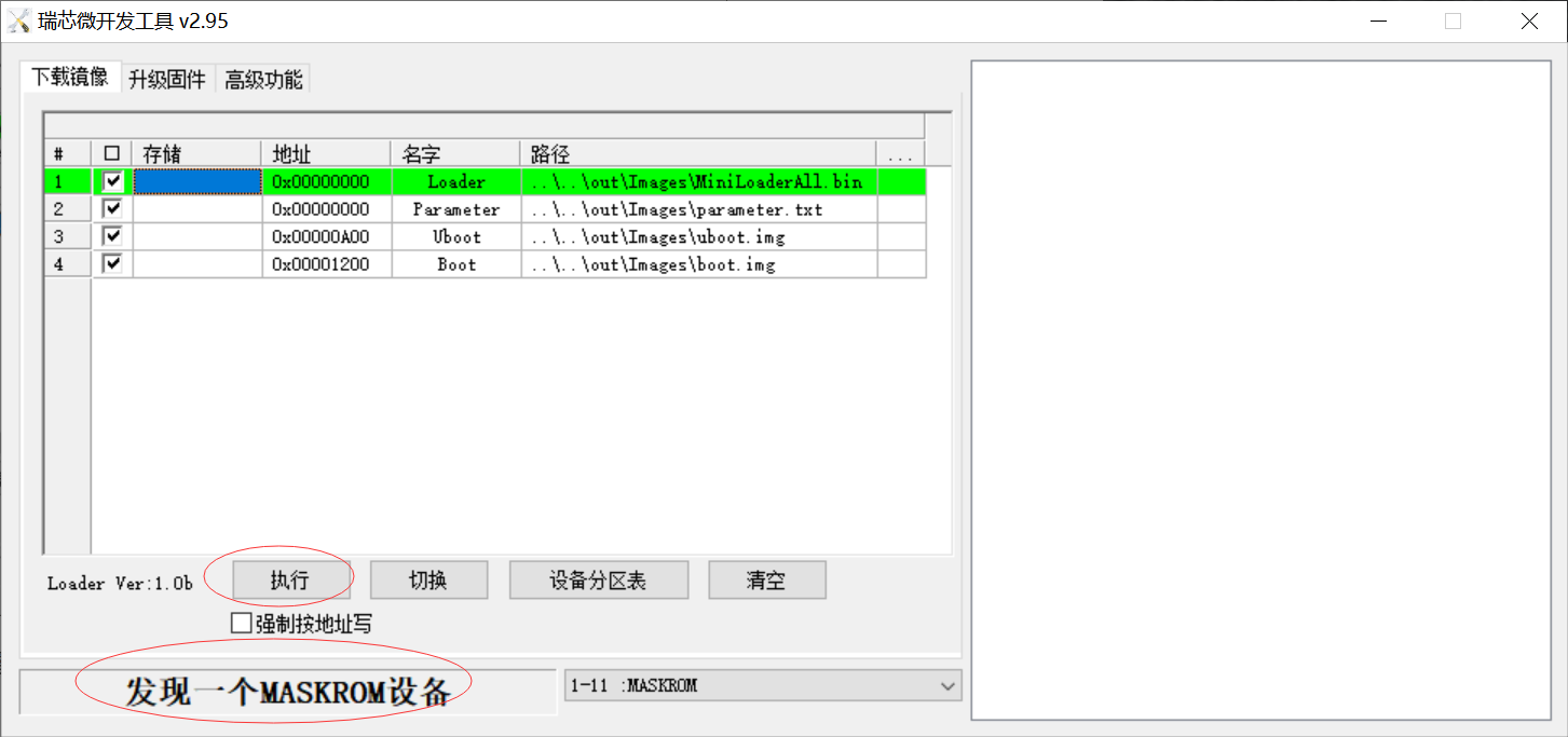
Found One MASKROM Device (as shown in Figure 1-6): Indicating that the development board entered maskrom mode.
Upgrade Images via Linux Hsot
Upgrade All Images
Flash those images:MiniLoaderAll.bin, uboot.img, boot.img and parameter.txt
./edge flash -a
Upgrade Uboot Image
Flash images:MiniLoaderAll.bin,uboot.img and parameter.txt
./edge flash -u
Upgrade Kernel Image
Flash images: boot.img和resource.img
./edge flash -k
Help
Execute the following command to view the supported flash parameters.
./edge flash -h
Upgrade Rootfs image via TF-Card
Format the TF card into one partition
Format the TF card to ext4 file system on a Linux host (ensure that only the TF card reader is inserted as the USB storage device, assuming the TF card reader is recognized as /dev/sdb1)
sudo mkfs.ext4 /dev/sdb1
Write the Rootfs.img image in the OUT_DIR directory to the TF card.
sudo dd if=OUT_DIR/rootfs.img of=/dev/sdb1
Upgrade Images via Windows Host
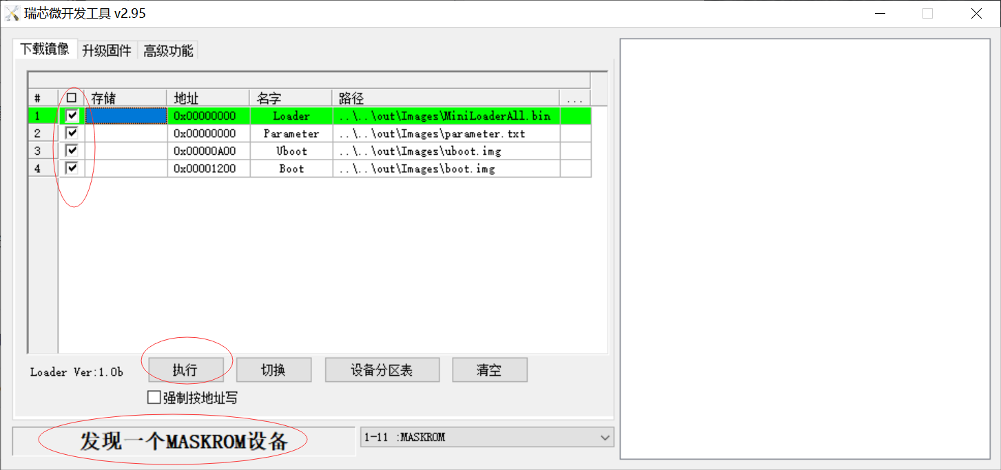
Open RKDevTool.exe in tools\RKDevTool_Release_v2.84 directory.
Verify development board has entered loader or maskrom mode.
Select the needed images to flash
备注
Loader and Parmeter are recommended, other options selected as needed.
Click “Execute” button to start flash images. (as shown in figure1-7).
Rootfs image upgrate refer toUpgrade Rootfs image via TF-Card
Running mode
Full-speed Mode
Connect to the power board, and powering on with a 12V power supply will enter full-speed mode.
The serial port log during the uboot stage in full-speed mode is as follows:

In the serial port log during the kernel stage, the command line displays the
performance_modeattribute asfull:
High-speed Mode
When an adapter supporting PD2.0/3.0 protocol is connected to the Type-C port marked with “POWER_IN” using a Type-C cable, it will enter high-speed mode upon powering on.
The serial port log during the uboot stage in high-speed mode is as follows:

In the serial port log during the kernel stage, the command line displays the
performance_modeattribute ashigh:
Low-speed Mode
Apart from the above two running mode, the device will enter low-speed mode.
The serial port log during the uboot stage in low-speed mode is as follows:

In the serial port log during the kernel stage, the command line displays the
performance_modeattribute aslow:
Boot the System
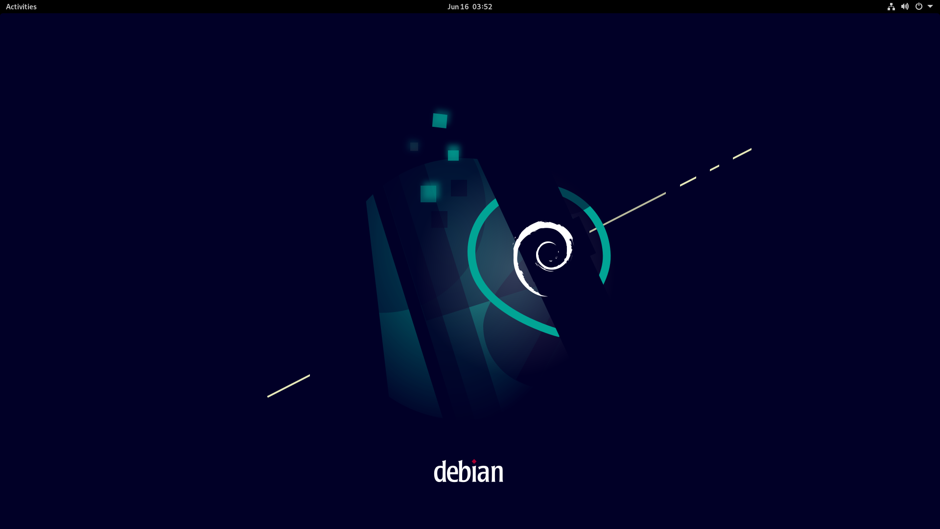
Insert the SD card, connect the HDMI display, boot up the Debian 11 system, and upon entering the system, you will see an interface similar to the following:
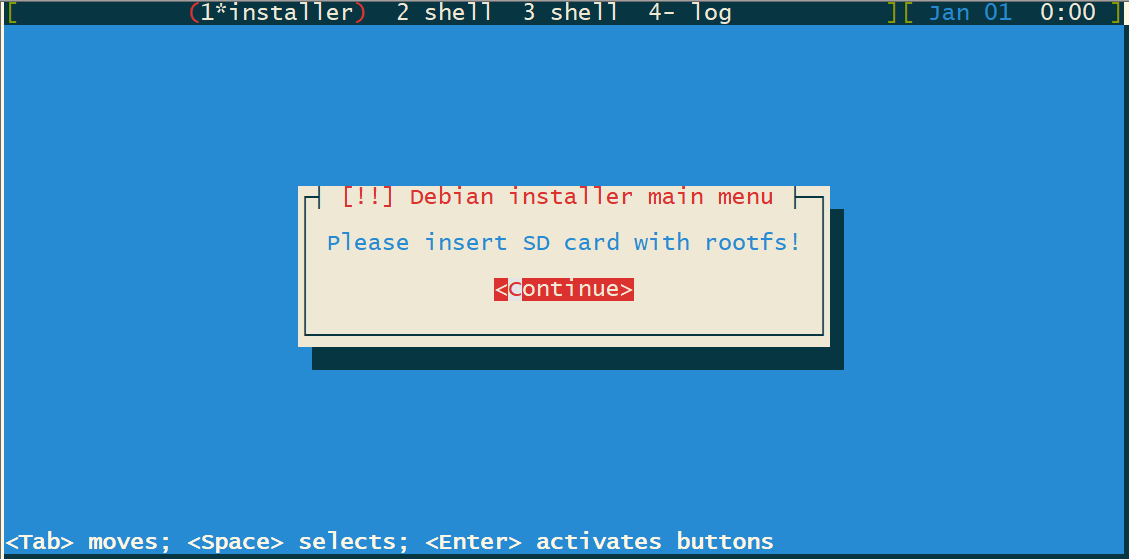
Without inserting the SD card, boot the system using the boot partition. The serial interface will display a prompt similar to the following. Please insert the SD card pre-installed with rootfs.img according to the prompt, select the “Continue” button, and press Enter to restart the system.
Note: Avoid hot-plugging the SD card. Please insert the SD card after powering off the device!
